All you need to know about the Arduino Hardware👩🏻💻
Arduino Series Part 2
Let’s know how the board looks like and all its components.
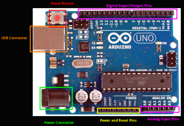
The reset button just to RESET the Arduino. The USB Connector is used to connect the Arduino to the PC. For small projects involving sensors or other basic electronic components this USB Port also serves as the power source. The external Power Connector in the form of a barrel jack is only used for high power operations.
Now coming to the I/O pins which are present on either side of the board to interact with the external world like taking physical inputs from the environment, sensors or displaying output to some external display etc. (These are simply holes where we fit in maybe, jumper wires).
Digital pins at the top are responsible for taking both input and producing output. These pins take discrete values (say 0V and 5V for this Arduino model) coming to the board via the pins i.e. 0 →0 V and 1 → 5V. For Analog inputs (i.e anything between (0–5)V), we use the 6 pins towards the bottom of the board. These pins can’t drive Analog outputs. Towards the left of the Analog pins, we have the various power pins like 5V, 3.3 V and several grounds which are frequently used to drive the circuits.
The key component of the Arduino board are the two microcontroller chips although only one is important or will be most used by the users. They are ATmega328 and ATmega16U2. ATmega328 is the one we program as users and ATmega16U2 is the one used for USB communication. The latter uses some USB protocol to communicate with the USB port and in turn, helps the ATmega328 to understand the to and fro USB data. As users we can only access ATmega328 and play with it. ATmega16U2 is pre-programmed and thus can’t be coded or changed directly.
Any microcontroller will have an application code which we program in the IDE and make things work and the Firmware which we can think of as some low level code which supports the main function like setting power modes, talking to the USB etc and mostly always pre-programmed.
Bootloader — It is a firmware on the microcontroller which allows the program to be copied to Flash Memory and EEPROM of the ATmega328 and rewrite codes to it. The bootloader is pre burned in the Arduino. However a bootloader can’t reprogram itself i.e we can’tmimicked update the bootloader using the normal USB interface so a special programming method is required to program the firmware using the In-Circuit Serial Programming interface. The bootloader can be programmed or updated through this ICSP pins. There are two ICSP headers for the two processors in the Arduino board.
Let’s talk briefly about the schematics of the Arduino: You can check the official arduino schematics here. We can see the wirings and connections in the schematic drawings which are exactly mimicked in the physical board. However, the layout and the scale is not exactly as in the board.
Coursery : Slides from Prof Ian Harris Lectures
So, that’s it about the hardware specifications we need to know about the microcontroller before starting to code. In general, when we write a program(say blink LED) in the arduino IDE and upload it to the board, the board resets and the bootloader runs . The bootloader then writes the program to the Flash memory of the ATmega328 to let use for our applications. I will talk about the entire programming workflow of the microcontroller in the next post.
Stay tuned!
References:
- An Introduction to Programming the IOT Specialization by UCI and Coursera